Posts

Showing posts from June, 2011

UART & RS232

Image
Universal Asynchronous Transmitter Receiver LSB first.Each character is sent as a logic low start bit , a configurable number of data bits (usually 7 or 8, sometimes 5), an optional parity bit, and one or more logic high stop bits . RS232 is standard to control the signaling RTS/CTS handshaking: DTE assert Ready to send (RTS) signal to DCE ,DCE reply by asserting Clear to send (CTS) in older RS232,Still in RS-232 to RS-485 bus converter use this mechanism to check bus mastering. DTE :data terminating Equipment (e.g. desktop) DCE:data circuit terminating equipment
I2C and SPI

Good links on I2C (inter integrated circuit) http://www.robot-electronics.co.uk/acatalog/I2C_Tutorial.html http://en.wikipedia.org/wiki/I%C2%B2C (400 kbit/s Fast mode , 1 Mbit/s Fast mode plus or Fm+, and 3.4Mbits/s High Speed mode ) A master loses arbitration when it cannot get either SCL or SDA to go high when needed, this problem does not exist. It is the device that is sending the '0' that rules the bus. One master cannot disturb the other master's transmission because if it can't detect one of the lines to go high, it backs off, and if it is the other master that can't do so, it will behave the same. This kind of back-off condition will only occur if the two levels transmitted by the two masters are not the same. Therefore, let's have a look at the following figure, where two MCUs start transmitting at the same time: Good links on SPI (serial peripheral interface) http://en.wikipedia.org/wiki/Serial_Peripheral_Interface_Bus ww1.microchip.com/

When to use volatile

an object that is a memory-mapped I/O port an object that is shared between multiple concurrent processes an object that is modified by an asynchronous signal handler an automatic storage duration object declared in a function that calls setjmp and whose value is changed between the call to setjmp and a corresponding call to longjmp For details refer :http://www.programmersheaven.com/articles/pathak/article1.htm

USB enumeration short Steps

1) Hub/root detect device is whether high/full speed by detecting D+ and D- pull up signaling(reset and wait for atleast for 10ms and check using J and K states of signaling{check JKJKJK pattern]) and create data path between host and device after notifying root by Interrupt end point interrupt. 2) Host send get device descriptor to address 00h,endpoint zero to get max packet size of default pipe.though the request is for 64 byte descriptor at 8th byte size is found and status status stage of the transfer. 3)Host reset the device. 4) Host set the device address using SET ADDRESS 5)Host send Device descriptor request to learn device ability and other functions.It learns furter by requesting configuration descriptors ,and other subordinate descriptors (interface decriptor vendor specific descriptors etc.) 6) After learning from configuration descriptors host match best suitable driver for it and load it. 7) Host driver may select one configuration may request further configur

PPC Register classification

r0 local commonly used to hold the old link register when building the stack frame r1 dedicated stack pointer r2 dedicated table of contents pointer r3 local commonly used as the return value of a function, and also the first argument in r4–r10 local commonly used to send in arguments 2 through 8 into a function r11–r12 local r13–r31 global lr dedicated link register; cannot be used as a general register. Use mflr (move from link register) or mtlr (move to link register) to get at, e.g., mtlr r0 cr dedicated condition register More :http://www.csd.uwo.ca/~mburrel/stuff/ppc-asm.html

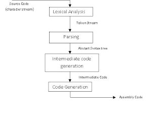
Compilation steps

Image
Lexical analysis Syntax analysis Semantic analysis Pre-optimization of internal representation. Intermediate code generation Post Code optimization Target code generation.